In
CMCP570 Solid State Temperature Transmitter/Monitor
☰
filters
Solid State Temperature Transmitter/Monitor CMCP570
Key features:
- Solid State Temp. Input
- Temperature Output
- Transmitter or Monitor
- Voltage Detection
- Type “T” Accelerometers
- 4-20 mA Output
- 2 Buffered Outputs
- 5 Selectable Ranges
- Fault (OK) Detection
- CSA & UL C1,D2
- DIN Rail Mount.
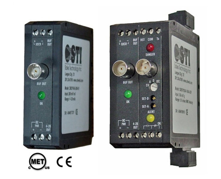
The CMCP570 Solid State Temperature Transmitter is compatible with Accelerometers with internal solid state temperature sensing elements such as the 793T and 797T. It is available in English or Metric scaling. The CMCP565 provides constant current power, checks for faults, processes the temperature signal to determine overall amplitude, and outputs a 4-20 mA dc current that is proportional to a range of 0 to 250° F (-17.8 to 121°C). Combining transmitters with an existing PLC or DCS system results in a high density, low cost vibration monitoring system. The Optional Alarm Module provides ok, alert and danger relays, selectable time delay, trip multiply, bypass and 0 to 5 VDC outputs for displays. The relay outputs can be used to trigger machine shut-down or other alarms. Combining transmitters with an existing PLC or DCS system results in a high density, low cost vibration monitoring system. Alarms relays and trip multiply are available with the Monitor version.  Alarms – The CMCP500A Series Monitors have two independent set points, with LED alarm indicators and output relay contacts (Alert and Danger). Set points are adjustable via potentiometer, from 0 to 110% of full scale. Each has an adjustable delay of 1 to 10 seconds. SPST Relay contacts are rated 5 Amps @ 30 Vdc or 250 Vac for resistive loads. Relay contacts can be independently configured by the user for either Normally Open (NO) (Standard) or Normally Closed (NC) operation. Relays are normally de-energized and can be configured for latching or non-latching (standard) operation. Latched alarms may be reset locally or by remote contact closure. Trip Multiply – The monitors have set point multiplication of 3X via contact closure (2X available). To avoid tripping the alarms during machine start-up.
 Alarms – The CMCP500A Series Monitors have two independent set points, with LED alarm indicators and output relay contacts (Alert and Danger). Set points are adjustable via potentiometer, from 0 to 110% of full scale. Each has an adjustable delay of 1 to 10 seconds. SPST Relay contacts are rated 5 Amps @ 30 Vdc or 250 Vac for resistive loads. Relay contacts can be independently configured by the user for either Normally Open (NO) (Standard) or Normally Closed (NC) operation. Relays are normally de-energized and can be configured for latching or non-latching (standard) operation. Latched alarms may be reset locally or by remote contact closure. Trip Multiply – The monitors have set point multiplication of 3X via contact closure (2X available). To avoid tripping the alarms during machine start-up.
 Fault Detection:
On board fault detection circuitry continuously monitors the transducer for normal operation. If a fault occurs, the output current is reduced to <2 mA to indicate the fault to the readout system. A green LED on the front of the unit is turned off to provide a local indication of the fault.
Technical Specs:
| Electrical |
|---|
| Input: Accelerometers with Solid State Temperature. (793T and 797T) |
| Power: +24 Vdc @ 45 mA max. (30 mA typical) |
| Protection: Reverse polarity and transient protection |
| Frequency Response (wo/filters): (-3 dB) 2 Hz to 20 kHz |
| Buffered Output: BNC Connector 0-20 kHz |
| Accuracy: 0.5 % of Full Scale Range |
| Output: 4-20 mA proportional to the full scale range |
| Maximum Load: 600 Ohms Resistive |
| Case: Isolated |
| Range: English, 0 to 250° F. Metric, 0 to 120° C. |
| Fault Indication: Green LED and 4-20 mA < 2mA |
| Optional Relay Module |
|---|
| Alarms: OK, Alert and Danger |
| Alarm Setpoints: Alert and Danger Adjustable 0 to 110% FS |
| Trip Multiply: 2X or 3X on Contact Closure |
| Alarm Relays: OK, Alert and Danger |
| Form C, SPDT, 5A @ 30 VDC or 250 VAC |
| Latching or Non-latching, Selectable |
| Time Delay: 0.1, 1, 3, 6 or 10 Seconds, Selectable |
| Alarm LED’s: Alert = Yellow, Danger = Red |
| Display Outputs: 0-5 VDC for Current Value, Alert Setpoint and Danger Setpoint |
| Environmental |
|---|
| Operating Temp.: -20°C to +80° C (-4° F to +176° F) |
| Storage Temp.: -55°C to +125° C (-67° F to +257° F) |
| Relative Humidity: 0 – 95% Non-Condensing |
| Physical |
|---|
| Mounting: 32 mm (G style) or 35 mm (T style) DIN Rail |
| Size: Transmitter 1.0″ Wide x 3.11″ High x 3.95″ Deep |
| w/Relay Module 1.6″ Wide x 3.11″ High x 3.95″ Deep |


