In
CMCP530 Velocity Transmitter/Monitor
☰
filters
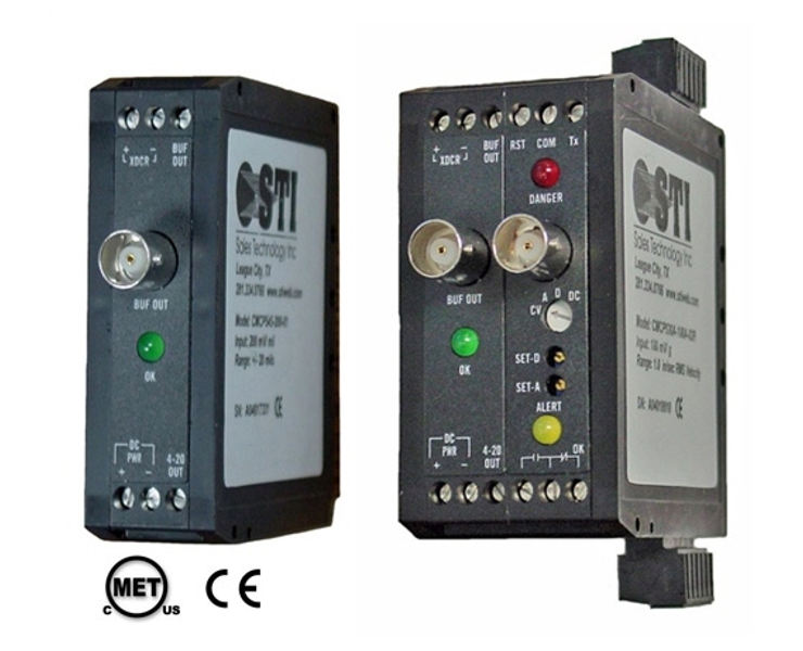
CMCP530 Velocity Transmitter/Monitor
Key features:- Accelerometer Input
- Velocity Output
- Transmitter or Monitor
- RMS or Peak Detection
- 100 mV/g Input Std.
- 4-20 mA Output
- 2 Buffered Outputs
- 5 Selectable Ranges
- Fault (OK) Detection
- CSA & UL C1,D2
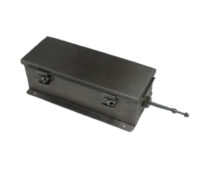
- DIN Rail Mount
- Optional HP & LP Filters
The Optional Alarm Module provides ok, alert and danger relays, selectable time delay, trip multiply, bypass and 0 to 5 VDC outputs for displays. The relay outputs can be used to trigger machine shut-down or other alarms.
Alarms relays and trip multiply are available with the Monitor version.
 Alarms – The CMCP500A Series Monitors have two independent set points, with LED alarm indicators and output relay contacts (Alert and Danger). Set points are adjustable via potentiometer, from 0 to 110% of full scale. Each has an adjustable delay of 1 to 10 seconds. SPST Relay contacts are rated 5 Amps @ 30 Vdc or 250 Vac for resistive loads. Relay contacts can be independently configured by the user for either Normally Open (NO) (Standard) or Normally Closed (NC) operation. Relays are normally de-energized and can be configured for latching or non-latching (standard) operation. Latched alarms may be reset locally or by remote contact closure. Trip Multiply – The monitors have set point multiplication of 3X via contact closure (2X available). To avoid tripping the alarms during machine start-up. Custom Input and Output Calibrations are Available on Request.
Buffered Output: A BNC connector mounted on the front of the unit provides access to the buffered transducer output signal. This includes both the unfiltered vibration signal, and the DC bias voltage. Portable test equipment or analyzers can be connected to this output without disturbing other system outputs. Fault Detection: On board fault detection circuitry continuously monitors the transducer for normal operation. If a fault occurs, the output current is reduced to <2 mA to indicate the fault to the readout system. A green LED on the front of the unit is turned off to provide a local indication of the fault. Filters:Alarms – The CMCP500A Series Monitors have two independent set points, with LED alarm indicators and output relay contacts (Alert and Danger). Set points are adjustable via potentiometer, from 0 to 110% of full scale. Each has an adjustable delay of 1 to 10 seconds. SPST Relay contacts are rated 5 Amps @ 30 Vdc or 250 Vac for resistive loads. Relay contacts can be independently configured by the user for either Normally Open (NO) (Standard) or Normally Closed (NC) operation. Relays are normally de-energized and can be configured for latching or non-latching (standard) operation. Latched alarms may be reset locally or by remote contact closure. Trip Multiply – The monitors have set point multiplication of 3X via contact closure (2X available). To avoid tripping the alarms during machine start-up. Custom Input and Output Calibrations are Available on Request.For applications that require monitoring specific frequency bands, optional high-pass and low-pass filters can be specified. These filters are modular and can be installed by the factory or in the field. Each module attenuates out-of-band signals at a rate of approximately 24 dB/octave. Corner frequencies from 2 Hz to 20 kHz may be specified. Filter modules may be cascaded to form higher order filters or to create a band-pass response. Filtering does not effect the buffered transducer output.
Technical Specs:| Electrical |
|---|
| Input: Accelerometer (100 mv/g) |
| Power: +24 Vdc @ 45 mA max. (30 mA typical) |
| Protection: Reverse polarity and transient protection |
| Frequency Response (wo/filters): (-3 dB) 2 Hz to 20 kHz |
| Buffered Output: BNC Connector 0-20 kHz |
| Accuracy: 0.5 % of Full Scale Range |
| Output: 4-20 mA proportional to the full scale range |
| Maximum Load: 600 Ohms Resistive |
| Case: Isolated |
| Range: English, 0.5, 1.0, 1.5, 2.0, or 2.5 in/sec. or Metric, 12.5, 25.4, 38.1, 50.8, 63.5 mm/sec. |
| Constant Current Diode: 4.0 mA |
| Fault Indication: Green LED and 4-20 mA < 2mA |
| Optional Relay Module |
|---|
| Alarms: OK, Alert and Danger |
| Alarm Setpoints: Alert and Danger Adjustable 0 to 110% FS |
| Trip Multiply: 2X or 3X on Contact Closure |
| Alarm Relays: OK, Alert and Danger |
| Form C, SPDT, 5A @ 30 VDC or 250 VAC |
| Latching or Non-latching, Selectable |
| Time Delay: 0.1, 1, 3, 6 or 10 Seconds, Selectable |
| Alarm LED’s: Alert = Yellow, Danger = Red |
| Display Outputs: 0-5 VDC for Current Value, Alert Setpoint and Danger Setpoint |
| Environmental |
|---|
| Operating Temp.: -20°C to +80° C (-4° F to +176° F) |
| Storage Temp.: -55°C to +125° C (-67° F to +257° F) |
| Relative Humidity: 0 – 95% Non-Condensing |
| Physical |
|---|
| Mounting: 32 mm (G style) or 35 mm (T style) DIN Rail |
| Size: Transmitter 1.0″ Wide x 3.11″ High x 3.95″ Deep |
| w/Relay Module 1.6″ Wide x 3.11″ High x 3.95″ Deep |